UHF Hentenna
I wanted a portable some what directional UHF antenna that I could use for path testing for linking for some time and after looking over a bunch of different Google search results I decided to try making a Hentenna. The Hentenna from the research I’ve done has 2 – 3 dbd gain in a bi-directional pattern. The directions I based my build on are located at Ham Universe.
They give you the formulas for the dimensions and the lay out.
I had a piece of 1/4″ copper tubing sitting around so I figured for my first attempt at a Hentenna it would work great.
For the actual I didn’t have a tubing bender handy at the time but I did have some 3/16″ stainless steel cable that I fed through the tube to keep it from collapsing when I bent the tube into the rectangular shape of the antenna.
My first bend was at 5.6mm from one end (half of the short side distance) then worked my way around until I completed all four bends. Then I verified the short side length and cut the extra copper tubing off the end so that when the two ends but together I got 11.2mm centre to centre.
I joined the two ends by inserting a short piece of #12 stranded bare copper wire in the tube to provide some rigidity while I soldered the to end together.
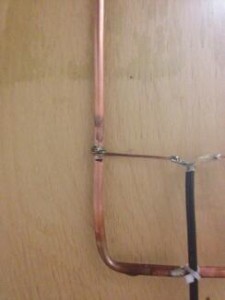
For the feed point I cut a length of #14 bare copper wire and laid it across the antenna at the calculated feed point location and curled the ends around the tubing.
I then marked the centre point of #14 copper wire.
On the coax feed line I stripped back approximately 1″ of outer sheath then pulled back the braid and twisted off to one side. I striped about 3/8″ of the centre conductor.
I formed the end of the coax into a “T” shape, centred the “T” on the #14 copper wire then soldered the shield and the centre conductor to the #14 wire. Once they where soldered I used my flush cutters to cut the #14 wire between the two solder joints out.
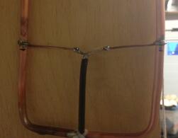
I tie wrapped the coax on the the antenna to relieve the strain on the feed points.
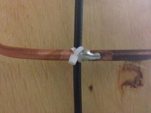
Now it was time to tune the antenna.
I used my antenna analyser to check the SWR of the antenna and I adjusted it for the minimum SWR at 446 mhz by sliding the #14 wires up slightly from the measured feed point. I was able to get less then 1.5 SWR across most of the band.
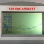
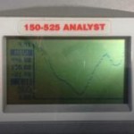 10 mHz and 100 mHz scan widths centred on 446 mHz
After tuning I soldered the 2 pieces of #14 wire to the 1/4″ tubing then verified the antenna was still in tune.
Here’s the completed antenna.

For horizontal polarization mount the antenna on a non-conducting mount with the short sides at the top and bottom. For vertical polarization, mount the antenna with the short sides vertically.
Initial testing shows that it is an improvement over a 1/4″ wave ground plane antenna.
Leave a Reply