Digital Controlled Solar Heater
At the end of February I attended the Peace River Sun Day Solar Workshop hosted by the Webberville Community Forest Association. One of the presentations near the end they showed us a screen solar heater design that had evolved from the pop can solar heater that involves building a box with black painted pop cans inside of it and a window on the front and allowing air to pass through to “collect’ the heat energy and vent it into a building or green house.
I’m planning on building a portable green house to put over our vegetable garden this spring to try and get a few more weeks of growing on either end of the season, and this looked like an easy way to help heat this green house.
The various DIY plans on the internet show a small pc fan connected to a mechanical thermostat to move the air through the heater. But being an electronics geek I figured I could build a better control system for minimal cost that would increase the efficiency of the heater.
My idea was to use an Arduino, a couple 1-wire temperature sensors, and a relay to control the fan. My thinking was that a fixed mechanical thermostat wouldn’t turn the fan on during the colder mornings even though the sun was already heating the air in the box because the thermostat value was to high. So why not turn the fan on based on a temperature differential between the area we want to heat and the inside of the heater. That way if it’s 0°C in the green house and 5°C in the heater the fan would turn out and start heating rather the waiting until the heater is much hotter.
So I went online and sourced some sealed water proof 1-wire sensors and a 5 volt relay that the Arduino could easily power. Total bill for the parts was under $15 Canadian.
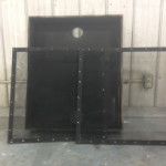
While I was waiting for the ordered parts to come in I started work on the rest of the heater. For the clear window on the front I used an old passenger window out of a helicopter that we had replaced at my day job. So that determined the size of my heater. The window once it was trimmed down to work was roughly 30″ x 36″.
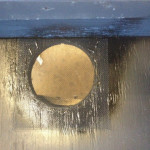
I had lots of scrap treated plywood around from other projects to build the box. So I picked up some black aluminum window screen and a can of flat black paint and started building. The intake and outlet holes are 3 1/2″, I decided on this size because the fan I had on hand for the project fit nicely over the hole.

For the screen frames to calculate the size, I measured 1.5″ from the out side lip of the top of the box as my material was 3/4″ that I was building the frame out of. The distance from that point to the top of the lower hole (intake) is the length of the screen frame. This allows the screens to be mounted on an angle so the air comes in on the front side of the screens and must pass through the screens to exit picking up heat along the way. The width of the frames is the inside dimension going across the box.
Once I constructed the frames, I stapled screen to two sides of one frame and one side of the other so that they could be be arranged to give 3/4″ spacing between the layers of screen.
I drilled a 3/8″ hole beside the inlet where my 1-wire temperature sensor for the outside or inlet temperature would be read. Then mounted the fan on the inside of the box over the upper hole. I attached my inside 1-wire temperature sensor to the top of the fan near the back of the box so it would be some what sheltered from direct sunlight and get a more accurate reading of the air temperature inside the heater at the outlet.


The fan that I found in the junk box was a “4 Wire” type pc cooling fan. I’ve played with these in the past the first two wire are your normal 12Vdc power wires the third one is connected to a speed sensor. The fourth one is fan speed control.
Pulse Width Modulation (PWM) is used to control the speed of the fan, it just so happens that Arduinos have PWM outputs built in, so I though ‘Hey why not in addition to turning the fan on based a temperature differential, vary the speed based on that same differential.’ should be easy to do…..
Well turns out the Arduino PWM is around 500Hz but PC fans are designed to used PWM frequencies between 30kHz and 300kHz. While it will work you can’t get the full speed range out of the fan. So after some searching on the net I found this function which allowed my to set the fan speed control pin on the Arduino to 31.25 kHz.
Here’s the current code which I plan on updating for an Arduino Pro Mini with no display in the near fut
|
1 2 3 4 5 6 7 8 9 10 11 12 13 14 15 16 17 18 19 20 21 22 23 24 25 26 27 28 29 30 31 32 33 34 35 36 37 38 39 40 41 42 43 44 45 46 47 48 49 50 51 52 53 54 55 56 57 58 59 60 61 62 63 64 65 66 67 68 69 70 71 72 73 74 75 76 77 78 79 80 81 82 83 84 85 86 87 88 89 90 91 92 93 94 95 96 97 98 99 100 101 102 103 104 105 106 107 108 109 110 111 112 113 114 115 116 117 118 119 120 121 122 123 124 125 126 127 128 129 130 131 132 133 134 135 136 137 138 139 140 141 142 143 144 145 146 147 148 149 150 151 152 153 154 155 156 157 158 159 160 161 162 163 164 165 166 167 168 169 170 171 172 173 174 175 176 177 178 179 180 181 182 183 184 185 186 187 188 189 190 191 192 193 194 195 196 197 198 199 200 |
// Solar Heater Fan Controller with 20 x 4 LCD Sketch // Description of Operation // // Using two 1-wire temperature sensors one on the inlet of the solar screen heater // and one in inside the heater in front of the oulet fan. The arduino compares the // temperatures and if there's a differnece of more then 5C a relay is closed turning // on power to a PC fan that is PWM speed controlled. // // Once the fan is turned on the speed is automaticly adjusted based on the temperature // difference. If the temp difference drops below 5C the relay contacts are opened and // the fan shuts off. // // The PWM output on Pin 9 must be adjusted to 31kHz by a function making a direct call // to the micro controller // Required Libraries #include <Wire.h> #include <LiquidCrystal_I2C.h> #include <OneWire.h> #include <DallasTemperature.h> // set the LCD address to 0x27 for a 20 chars 4 line display // Set the pins on the I2C chip used for LCD connections: // addr, en,rw,rs,d4,d5,d6,d7,bl,blpol LiquidCrystal_I2C lcd(0x27, 2, 1, 0, 4, 5, 6, 7, 3, POSITIVE); // Set the LCD I2C address // Data wire is plugged into pin 3 on the Arduino #define ONE_WIRE_BUS 3 // Setup a oneWire instance to communicate with any OneWire devices OneWire oneWire(ONE_WIRE_BUS); // Pass our oneWire reference to Dallas Temperature. DallasTemperature sensors(&oneWire); // Assign the addresses of your 1-Wire temp sensors. // See the tutorial on how to obtain these addresses: // http://www.hacktronics.com/Tutorials/arduino-1-wire-address-finder.html DeviceAddress insideThermometer = { 0x28, 0xFF, 0xB4, 0x8A, 0x65, 0x14, 0x01, 0xC3 }; DeviceAddress outsideThermometer = { 0x28, 0xFF, 0xDF, 0x3C, 0x65, 0x14, 0x01, 0x3A }; DeviceAddress soilThermometer = { 0x28, 0xFF, 0xF2, 0x8D, 0x65, 0x14, 0x01, 0x30 }; // Lets Define our variables int fanPin = 9; // Sets our fan speed control pin int fanSpeed = 0; // Sets the initial speed for the fan int fanRelay = 12; // The fan relay control pin int fanState = 1; // The fan state int diff = 1; //The temperature difference required to turn the fan on int tempDiff; float fanSpeedDisp; // Functions // See http://playground.arduino.cc/Code/PwmFrequency for details void setPwmFrequency(int pin, int divisor) { byte mode; if(pin == 5 || pin == 6 || pin == 9 || pin == 10) { switch(divisor) { case 1: mode = 0x01; break; case 8: mode = 0x02; break; case 64: mode = 0x03; break; case 256: mode = 0x04; break; case 1024: mode = 0x05; break; default: return; } if(pin == 5 || pin == 6) { TCCR0B = TCCR0B & 0b11111000 | mode; } else { TCCR1B = TCCR1B & 0b11111000 | mode; } } else if(pin == 3 || pin == 11) { switch(divisor) { case 1: mode = 0x01; break; case 8: mode = 0x02; break; case 32: mode = 0x03; break; case 64: mode = 0x04; break; case 128: mode = 0x05; break; case 256: mode = 0x06; break; case 1024: mode = 0x7; break; default: return; } TCCR2B = TCCR2B & 0b11111000 | mode; } } void setup() { pinMode(fanPin, OUTPUT); // initialize serial communication at 9600 bits per second: Serial.begin(9600); // Turn the LCD Back Light on lcd.backlight(); // finish with backlight on lcd.setBacklight(127); //Dims back light //Set Pin 9 PWM to 31.250 KHz setPwmFrequency(9, 1); lcd.begin(20,4); // initialize the lcd for 20 chars 4 lines, turn on backlight // Write LCD titles lcd.setCursor(0,0); lcd.print("OUTSIDE TEMP:"); lcd.setCursor(0,1); lcd.print("INSIDE TEMP:"); lcd.setCursor(0,2); lcd.print("EXT TEMP:"); lcd.setCursor(0,3); lcd.print("FAN SPEED:"); // Start up the 1-wire library sensors.begin(); // set the resolution to 10 bit (good enough?) sensors.setResolution(insideThermometer, 10); sensors.setResolution(outsideThermometer, 10); sensors.setResolution(soilThermometer, 10); // Set Fan relay pin mode pinMode(fanRelay, OUTPUT); } void loop() { delay(2000); Serial.print("Getting temperatures...\n\r"); sensors.requestTemperatures(); float inC=sensors.getTempC(insideThermometer); float outC=sensors.getTempC(outsideThermometer); float soilC=sensors.getTempC(soilThermometer); //Determin if the fan is needed float diffTemp = inC - outC; if(diffTemp >= diff) { digitalWrite(fanRelay, HIGH); fanState = 1; } else { digitalWrite (fanRelay, LOW); fanState = 0; int fanspeed = 0; } //Set fan speed if(fanState == 1){ fanSpeed = diffTemp * 5; // This factor gives 51 steps to 50C fanSpeed = (int) fanSpeed; if(fanSpeed > 255) { fanSpeed = 255; } analogWrite(fanPin, fanSpeed); Serial.print("Fan Speed: "); Serial.print(fanSpeed); Serial.print("\r\n"); float fanSpeedDispF = fanSpeed / 255.0 *100; fanSpeedDisp = (int)fanSpeedDispF; Serial.print("Fan Speed %: "); Serial.print(fanSpeedDisp); Serial.print("\r\n"); } // Display our values on the LCD lcd.setCursor(14, 0); lcd.print(outC); lcd.setCursor(14, 1); lcd.print(inC); lcd.setCursor(14, 2); lcd.print(soilC); lcd.setCursor(14, 3); lcd.print(fanSpeedDisp); //Clear the serial screen only works with putty etc. Serial.write(27); // ESC command Serial.print("[2J"); // clear screen command Serial.write(27); Serial.print("[H"); // cursor to home command //Write our values to the Serial Port Serial.print("Solar Heater Version 1 \n\r\n\r"); Serial.print("Outside Temp: "); Serial.print(outC); Serial.print(" C \n\r"); Serial.print("Inside Temp: "); Serial.print(inC); Serial.print(" C \n\r"); Serial.print("Temp Difference: "); Serial.print(diffTemp); Serial.print(" C \n\r"); Serial.print("Fan Speed: "); Serial.print(fanSpeedDisp); Serial.print("\n\r\n\r"); Serial.print("External Temp: "); Serial.print(soilC); Serial.print(" C \n\r\n\r"); //Pause the loop delay (1000); } |
The end result the controller is able to roughly maintain a 5 degree C differential. I did disable the fan at on time with an inlet temperature of 12C sitting in direct sunlight in March the heater was passively producing 56C air through convection only (44 degree increase).
Future plans are to convert it to a Arduino Pro Mini with no display, only serial out that can be sent to a data logger etc. Possibly an Arduino Yun based weather station?
0 Comments on “Digital Controlled Solar Heater”